| Name | Last Update | Last Commit ca223e0245c – orbimote avec soft endpoint dans field_test_device | history |
|---|---|---|---|
|
|
|||
|
|
|||
|
|
|||
|
|
|||
|
|
|||
|
|
|||
|
|
|||
|
|
|||
|
|
|||
|
|
|||
|
|
|||
|
|
|||
|
|
|||
|
|
|||
|
|
|||
|
|
|||
|
|
|||
|
|
|||
|
|
|||
|
|
|||
|
|
|||
|
|
|||
|
|
|||
|
|
|||
README.md
Field Test Device
Field Test Device
The program sends periodically LoRaWAN frames at various datarate and tx power.
If a NMEA0183 GNSS module is plugged onto the board, the postion is sent into each LoRaWAN frames. See the list of NMEA0183 GNSS module.
Uplink frames can be confirmed or unconfirmed by the network server.
The RTC of the board can be synchronized according to the App Clock Sync Specification.
Payload format
fPort : 2 to 170

uint8 : txpower (2,5,8,11,14) in dBm
uint8 : datarate (0,1,2,3,4,5)
int16 : temperature in 0.01 °C
int24 : latitude
int24 : longitude
int16 : altitude
The paylaod will include in a future version the following fields : downlink message counter (uint16_t), last downlink fCnt (uint16_t), last downlink RSSI (uint8_t), last downlink LSNR (int8_t) and GPIO_IN bitfield (uint8_t)
Boards
Board:
- [x] boards/im880b
- [x] OrbiMote (im880a)
- [x] nucleo-f446re + P-NUCLEO-LRWAN1
- [x] nucleo-f446re + SX1276MB1xAS for eu433 and eu868
- [ ] boards/b-l072z-lrwan1
- [ ] STM32WL55
- [ ] ESP32 Heltec LoRa
- [ ] ESP32 TTGO Beam
- [ ] Bluepill + RFM9x
- [ ] Generic Node
- [ ] LilyGo (SX1262)
- [ ] all boards with Microchip RN2483 module
Default board
The IMST iM880a board is a simple prototyping board with an IMST IMST iM880a LoRa module a DS75LX temperature sensor. The TX pin of a NMEA0183 GNSS module can be plugged on the pin 10 (Rx) of connector X2 (with 3V3 on pin 11 and GND on pin 12).
Libraries
Packages & Drivers:
GPS modules:
Build and flash
Connect the X1 and X2 connectors according to the wiring despicted in the annexes.
Register the endpoint into a LoRaWAN network (public or private) using the DevEUI, the AppEUI and the AppKey (displayed into the console).
Build the firmware
export RIOTBASE=~/github/RIOT-OS/RIOT
(cd $RIOTBASE; git checkout 6bf6b6be6c4723b49f62550a35111e57b7426aa4)
make binfile
Connect the board to the STLink according this tutorial and then flash the firmware
export RIOTBASE=~/github/RIOT-OS/RIOT
make flash-only
Setting DEVEUI APPEUI APPKEY
By default, the DevEUI, the AppEUI and the AppKey are forged using the CPU ID of the MCU. However, you can set the DevEUI, the AppEUI and the AppKey of the LoRaWAN endpoint into the main.c.
Optional : Configure the following parameters into the program file main.c : FIRST_TX_PERIOD, TX_PERIOD, DR_INIT, ADR_ON, DEBUG_ON and SECRET.
make SECRET=cafebabe02ffffffcafebabe02000001 binfile
The AppKey can be recovered from the DevEUI (displayed at startup) and the SECRET (flashed into the firmware) with the command lines below:
SECRET=cafebabe02000001cafebabe02ffffff
DevEUI=33323431007f1234
AppEUI=33323431ffffffff
SHA=$(echo -n $DevEUI$AppEUI$SECRET | xxd -r -p | shasum -b | awk '{print $1}')
AppKey="${SHA:0:32}"
echo $AppKey
The DevEUI, the AppEUI and the AppKey can be set by fixing DEVEUI APPEUI APPKEY into the make command
make DEVEUI=33323431007f1234 APPEUI=33323431ffffffff APPKEY=f482a62f0f1234ac960882a2e25f971b binfile
Enable/Disable the GNSS module
Edit Makefile or overload GPS and STD_BAUDRATE default values
GPS=0 make
GPS=1 STD_BAUDRATE=9600 make
GPS=1 STD_BAUDRATE=56700 make
if GPS is enabled, the console baudrate is 9600 b/s and not by default 115200 b/s.
Enable/Disable the region duty cycle
The region duty cycle can be enabled or disabled in the region file in bin/pkg/im880b/semtech-loramac/src/mac/region.
For instance, ~/github/RIOT-OS/RIOT/build/pkg/semtech-loramac/src/mac/region/RegionEU868.h for region EU868
Enable region duty cycle
#define EU868_DUTY_CYCLE_ENABLED 1
Disable region duty cycle
#define EU868_DUTY_CYCLE_ENABLED 0
Console
Connect the board TX pin to USBSerial port and then configure and start minicom or Pyterm.
if GPS is enabled, the baudrate is 9600 b/s. Else the baudrate is 115200 b/s.
ll /dev/tty.*
make term
or
ll /dev/tty.*
minicom -s
Downlink
The application can send a downlink message to the endpoint throught your network server.
Downlink payload can be used for
- sending an ASCII message (port = 1)
- setting the realtime clock of the endpoint (port = 2)
- setting the tx period of the data (port = 3)
Setup
For CampusIoT:
ORGID=<YOUR_ORG_ID>
BROKER=lns.campusiot.imag.fr
MQTTUSER=org-$ORGID
MQTTPASSWORD=<YOUR_ORG_TOKEN>
applicationID=1
devEUI=33323431007f1234
sending an ASCII message
PORT=1
mosquitto_pub -h $BROKER -u $MQTTUSER -P $MQTTPASSWORD -t "application/$applicationID/device/$devEUI/tx" -m '{"reference": "abcd1234","confirmed": true, "fPort": '$PORT',"data":"SGVsbG8gQ2FtcHVzSW9UICE="}'
The output on the console is:
main(): This is RIOT! (Version: 2020.04-devel-1660-gb535c)
Secret:cafebabe02000001cafebabe02ffffff
DevEUI:33323431007f1234
AppEUI:33323431ffffffff
AppKey:f482a62f0f1234ac960882a2e25f971b
Starting join procedure: dr=5
Join procedure succeeded
Sending LPP payload with : T: 22.75
Received ACK from network
Sending LPP payload with : T: 22.75
Data received: Hello CampusIoT !, port: 1
Received ACK from network
setting the tx period of the data
PORT=3
mosquitto_pub -h $BROKER -u $MQTTUSER -P $MQTTPASSWORD -t "application/$applicationID/device/$devEUI/tx" -m '{"reference": "abcd1234","confirmed": true, "fPort": '$PORT',"data":"PAA="}'
The new tx period is 60 seconds (3C00) The epoch is a unsigned 16 bit-long integer (big endian)
The output on the console is:
...
Sending LPP payload with : T: 22.75
Data received: tx_period=60, port: 3
Received ACK from network
Setting the realtime clock of the endpoint
PORT=202
PAYLOAD=FE0BF6FB4B
mosquitto_pub -h $BROKER -u $MQTTUSER -P $MQTTPASSWORD -t "application/$applicationID/device/$devEUI/tx" -m '{"reference": "abcd1234","confirmed": true, "fPort": '$PORT',"data":"/gv2+0s="}'
The time is the number of seconds since 06/01/1980 (GPS start time). It is unsigned 32 bit-long integer (big endian) LSBF
The output on the console is:
...
Received ACK from network
Current RTC time :   2020-05-24 15:03:09
Last correction  :   2020-05-24 15:00:49
Read temperature= 25.00
app_clock_process_downlink
X_APP_CLOCK_CID_AppTimeSetReq
Current time    :   2020-05-24 15:03:44
RTC time fixed  :   2020-05-24 16:08:43
sent_buffer:
Remark: Chirpstack implements the App Clock Sync Specification. The synchronization is done at the LNS level.
Annexes
TODO
- [ ] Add a downlink message counter (uint16_t), the last downlink fCnt (uint16_t), last downlink RSSI (uint8_t), last downlink LSNR (int8_t) and GPIO_IN bitfield (uint8_t) into the uplink payload
- [x] Downlink for configuring TxPeriod
- [ ] Downlink for reading GPIO_IN
- [ ] Downlink for setting GPIO_OUT (set or clear) for actuator control
- [ ] Downlink for configuring the DRPWSZ_SEQUENCE
- [ ] Downlink for configuring Confirmation
- [ ] Downlink for rejoining (see Certification Test)
- [ ] Downlink for setting ADR (see Certification Test)
- [ ] Class C endpoint ?
- [ ] Multiple ABP endpoints with DEVADDRS define
Base64 utils
Encode base64
echo 'Hello CampusIoT' | base64
echo '414243442045464748' | xxd -r -p | base64
Decode base64
echo SGVsbG8gQ2FtcHVzSW9UCg== | base64 -d
echo QUJDRCBFRkdI | base64 -d
IMST iM880a DS75LX Connectors

Connector X1
Connector X2
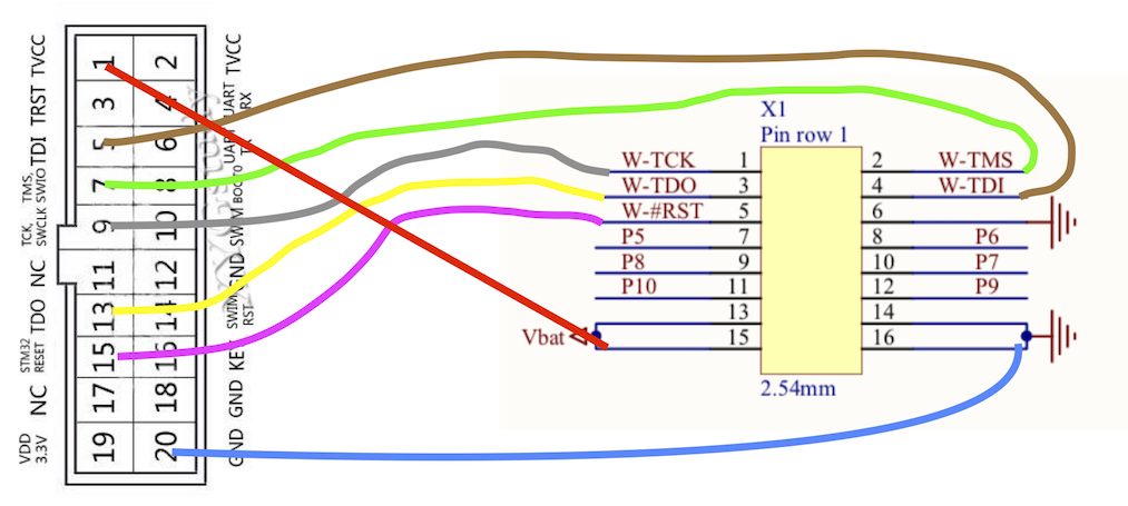
Note: if you do not have an ST-Link v2 flasher, you can use the ST-Link part of a Nucleo board and connect the first 5 pins of the CN4 SWD connector to the X1 connector of the IMST im880 board:
| Nucleo CN4 SWD | IMST X1 | Color |
|---|---|---|
| Pin 1: VDD_TARGET (VDD from application) | 15 | Red |
| Pin 2: SWCLK (clock) | 1 | Brown |
| Pin 3: GND (ground) | 16 | Black/Blue |
| Pin 4: SWDIO (SWD data input/output) | 2 | Green |
| Pin 5: NRST (RESET of target STM32) | 5 | Yellow |