Blame view
orbimote/field_test_device/README.md
11.5 KB
|
ca223e024
|
1 2 3 4 5 6 7 8 9 10 11 12 13 14 15 16 17 18 19 20 21 22 23 24 25 26 27 28 29 30 31 32 33 34 35 36 37 38 39 40 41 42 43 44 45 46 47 48 49 50 51 52 53 54 55 56 57 58 59 60 61 62 63 64 65 66 67 68 69 70 71 72 73 74 75 76 77 78 79 80 81 82 83 84 85 86 87 88 89 90 91 92 93 94 95 96 97 98 99 100 101 102 103 104 105 106 107 108 109 110 111 112 113 114 115 116 117 118 119 120 121 122 123 124 125 126 127 128 129 130 131 132 133 134 135 136 137 138 139 140 141 142 143 144 145 146 147 148 149 150 151 152 153 154 155 156 157 158 159 160 161 162 163 164 165 166 167 168 169 170 171 172 173 174 175 176 177 178 179 180 181 182 183 184 185 186 187 188 189 190 191 192 193 194 195 196 197 198 199 200 201 202 203 204 205 206 207 208 209 210 211 212 213 214 215 216 217 218 219 220 221 222 223 224 225 226 227 228 229 230 231 232 233 234 235 236 237 238 239 240 241 242 243 244 245 246 247 248 249 250 251 252 253 254 255 256 257 258 259 260 261 262 263 264 265 266 267 268 269 270 271 272 273 274 275 276 277 278 279 280 281 282 283 |
# Field Test Device
## Field Test Device
The program sends periodically LoRaWAN frames at various datarate and tx power.
If a NMEA0183 GNSS module is plugged onto the board, the postion is sent into each LoRaWAN frames. See the list of [NMEA0183 GNSS module](../gnss_modules.md).
Uplink frames can be confirmed or unconfirmed by the network server.
The RTC of the board can be synchronized according to the [App Clock Sync Specification](https://lora-alliance.org/resource-hub/lorawanr-application-layer-clock-synchronization-specification-v100).
## Payload format
fPort : 2 to 170
uint8 : txpower (2,5,8,11,14) in dBm
uint8 : datarate (0,1,2,3,4,5)
int16 : temperature in 0.01 °C
int24 : latitude
int24 : longitude
int16 : altitude
> The paylaod will include in a future version the following fields : downlink message counter (uint16_t), last downlink fCnt (uint16_t), last downlink RSSI (uint8_t), last downlink LSNR (int8_t) and GPIO_IN bitfield (uint8_t)
## Boards
Board:
* [x] [boards/im880b](https://github.com/RIOT-OS/RIOT/tree/master/boards/im880b)
* [x] [OrbiMote (im880a)](https://github.com/CampusIoT/orbimote)
* [x] [nucleo-f446re](https://github.com/RIOT-OS/RIOT/tree/master/boards/nucleo-f446re) + [P-NUCLEO-LRWAN1](https://www.st.com/en/evaluation-tools/p-nucleo-lrwan1.html)
* [x] [nucleo-f446re](https://github.com/RIOT-OS/RIOT/tree/master/boards/nucleo-f446re) + [SX1276MB1xAS](https://os.mbed.com/components/SX1276MB1xAS/) for eu433 and eu868
* [ ] [boards/b-l072z-lrwan1](https://github.com/RIOT-OS/RIOT/tree/master/boards/b-l072z-lrwan1)
* [ ] [STM32WL55](https://github.com/RIOT-OS/RIOT/tree/master/boards/nucleo-stm32wl55)
* [ ] [ESP32 Heltec LoRa](https://github.com/RIOT-OS/RIOT/tree/master/boards/esp32-heltec-lora32-v2)
* [ ] [ESP32 TTGO Beam](https://github.com/RIOT-OS/RIOT/blob/master/boards/esp32-ttgo-t-beam)
* [ ] [Bluepill](https://github.com/RIOT-OS/RIOT/tree/master/boards/bluepill-stm32f030c8) + [RFM9x](https://learn.adafruit.com/adafruit-rfm69hcw-and-rfm96-rfm95-rfm98-lora-packet-padio-breakouts/arduino-wiring)
* [ ] [Generic Node](https://www.genericnode.com/)
* [ ] LilyGo (SX1262)
* [ ] all boards with [Microchip RN2483 module](https://github.com/RIOT-OS/RIOT/tree/master/drivers/rn2xx3)
### Default board
The IMST iM880a board is a simple prototyping board with an IMST IMST iM880a LoRa module
a DS75LX temperature sensor. The TX pin of a [NMEA0183 GNSS module](../gnss_modules.md) can be plugged on the pin 10 (Rx) of connector X2 (with 3V3 on pin 11 and GND on pin 12).
<p align="center">
<img src="images/im880a-ds75lx.jpg" alt="iM880a-DS75LX" width="75%"/>
</p>
## Libraries
Packages & Drivers:
* [semtech-loramac](https://github.com/RIOT-OS/RIOT/tree/master/pkg/semtech-loramac)
* [cayenne-lpp](https://github.com/RIOT-OS/RIOT/tree/master/pkg/cayenne-lpp)
* [ds75lx](https://github.com/RIOT-OS/RIOT/tree/master/drivers/ds75lx)
GPS modules:
* [See notes](../gnss_modules.md)
## Build and flash
Connect the X1 and X2 connectors according to the wiring despicted in the annexes.
Register the endpoint into a LoRaWAN network (public or private) using the DevEUI, the AppEUI and the AppKey (displayed into the console).
Build the firmware
```bash
export RIOTBASE=~/github/RIOT-OS/RIOT
(cd $RIOTBASE; git checkout 6bf6b6be6c4723b49f62550a35111e57b7426aa4)
make binfile
```
Connect the board to the STLink according this [tutorial](https://github.com/CampusIoT/tutorial/tree/master/im880a) and then flash the firmware
```bash
export RIOTBASE=~/github/RIOT-OS/RIOT
make flash-only
```
## Setting DEVEUI APPEUI APPKEY
By default, the DevEUI, the AppEUI and the AppKey are forged using the CPU ID of the MCU. However, you can set the DevEUI, the AppEUI and the AppKey of the LoRaWAN endpoint into the `main.c`.
Optional : Configure the following parameters into the program file `main.c` : `FIRST_TX_PERIOD`, `TX_PERIOD`, `DR_INIT`, `ADR_ON`, `DEBUG_ON` and `SECRET`.
```bash
make SECRET=cafebabe02ffffffcafebabe02000001 binfile
```
The AppKey can be recovered from the DevEUI (displayed at startup) and the SECRET (flashed into the firmware) with the command lines below:
```bash
SECRET=cafebabe02000001cafebabe02ffffff
DevEUI=33323431007f1234
AppEUI=33323431ffffffff
SHA=$(echo -n $DevEUI$AppEUI$SECRET | xxd -r -p | shasum -b | awk '{print $1}')
AppKey="${SHA:0:32}"
echo $AppKey
```
The DevEUI, the AppEUI and the AppKey can be set by fixing DEVEUI APPEUI APPKEY into the `make` command
```bash
make DEVEUI=33323431007f1234 APPEUI=33323431ffffffff APPKEY=f482a62f0f1234ac960882a2e25f971b binfile
```
## Enable/Disable the GNSS module
Edit Makefile or overload GPS and STD_BAUDRATE default values
```bash
GPS=0 make
GPS=1 STD_BAUDRATE=9600 make
GPS=1 STD_BAUDRATE=56700 make
```
> if GPS is enabled, the console baudrate is 9600 b/s and not by default 115200 b/s.
## Enable/Disable the region duty cycle
The region duty cycle can be enabled or disabled in the region file in `bin/pkg/im880b/semtech-loramac/src/mac/region`.
For instance, `~/github/RIOT-OS/RIOT/build/pkg/semtech-loramac/src/mac/region/RegionEU868.h` for region `EU868`
Enable region duty cycle
```c
#define EU868_DUTY_CYCLE_ENABLED 1
```
Disable region duty cycle
```c
#define EU868_DUTY_CYCLE_ENABLED 0
```
## Console
Connect the board TX pin to USBSerial port and then configure and start `minicom` or `Pyterm`.
> if GPS is enabled, the baudrate is 9600 b/s. Else the baudrate is 115200 b/s.
```bash
ll /dev/tty.*
make term
```
or
```bash
ll /dev/tty.*
minicom -s
```
## Downlink
The application can send a downlink message to the endpoint throught your network server.
Downlink payload can be used for
* sending an ASCII message (port = 1)
* setting the realtime clock of the endpoint (port = 2)
* setting the tx period of the data (port = 3)
### Setup
For CampusIoT:
```bash
ORGID=<YOUR_ORG_ID>
BROKER=lns.campusiot.imag.fr
MQTTUSER=org-$ORGID
MQTTPASSWORD=<YOUR_ORG_TOKEN>
applicationID=1
devEUI=33323431007f1234
```
### sending an ASCII message
```bash
PORT=1
mosquitto_pub -h $BROKER -u $MQTTUSER -P $MQTTPASSWORD -t "application/$applicationID/device/$devEUI/tx" -m '{"reference": "abcd1234","confirmed": true, "fPort": '$PORT',"data":"SGVsbG8gQ2FtcHVzSW9UICE="}'
```
The output on the console is:
```bash
main(): This is RIOT! (Version: 2020.04-devel-1660-gb535c)
Secret:cafebabe02000001cafebabe02ffffff
DevEUI:33323431007f1234
AppEUI:33323431ffffffff
AppKey:f482a62f0f1234ac960882a2e25f971b
Starting join procedure: dr=5
Join procedure succeeded
Sending LPP payload with : T: 22.75
Received ACK from network
Sending LPP payload with : T: 22.75
Data received: Hello CampusIoT !, port: 1
Received ACK from network
```
### setting the tx period of the data
```bash
PORT=3
mosquitto_pub -h $BROKER -u $MQTTUSER -P $MQTTPASSWORD -t "application/$applicationID/device/$devEUI/tx" -m '{"reference": "abcd1234","confirmed": true, "fPort": '$PORT',"data":"PAA="}'
```
> The new tx period is 60 seconds (3C00)
> The epoch is a unsigned 16 bit-long integer (big endian)
The output on the console is:
```bash
...
Sending LPP payload with : T: 22.75
Data received: tx_period=60, port: 3
Received ACK from network
```
### Setting the realtime clock of the endpoint
```bash
PORT=202
PAYLOAD=FE0BF6FB4B
mosquitto_pub -h $BROKER -u $MQTTUSER -P $MQTTPASSWORD -t "application/$applicationID/device/$devEUI/tx" -m '{"reference": "abcd1234","confirmed": true, "fPort": '$PORT',"data":"/gv2+0s="}'
```
> The time is the number of seconds since 06/01/1980 (GPS start time). It is unsigned 32 bit-long integer (big endian) LSBF
The output on the console is:
```bash
...
Received ACK from network
Current RTC time : 2020-05-24 15:03:09
Last correction : 2020-05-24 15:00:49
Read temperature= 25.00
app_clock_process_downlink
X_APP_CLOCK_CID_AppTimeSetReq
Current time : 2020-05-24 15:03:44
RTC time fixed : 2020-05-24 16:08:43
sent_buffer:
```
> Remark: Chirpstack implements the [App Clock Sync Specification](https://lora-alliance.org/resource-hub/lorawanr-application-layer-clock-synchronization-specification-v100). The synchronization is done at the LNS level.
## Annexes
## TODO
* [ ] Add a downlink message counter (uint16_t), the last downlink fCnt (uint16_t), last downlink RSSI (uint8_t), last downlink LSNR (int8_t) and GPIO_IN bitfield (uint8_t) into the uplink payload
* [x] Downlink for configuring TxPeriod
* [ ] Downlink for reading GPIO_IN
* [ ] Downlink for setting GPIO_OUT (set or clear) for actuator control
* [ ] Downlink for configuring the DRPWSZ_SEQUENCE
* [ ] Downlink for configuring Confirmation
* [ ] Downlink for rejoining (see Certification Test)
* [ ] Downlink for setting ADR (see Certification Test)
* [ ] Class C endpoint ?
* [ ] Multiple ABP endpoints with DEVADDRS define
## Base64 utils
Encode base64
```bash
echo 'Hello CampusIoT' | base64
echo '414243442045464748' | xxd -r -p | base64
```
Decode base64
```bash
echo SGVsbG8gQ2FtcHVzSW9UCg== | base64 -d
echo QUJDRCBFRkdI | base64 -d
```
### IMST iM880a DS75LX Connectors
<p align="center">
<img src="images/im880a-ds75lx.jpg" alt="iM880a-DS75LX" width="75%"/>
</p>

Connector X1
Connector X2
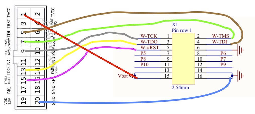
> Note: if you do not have an ST-Link v2 flasher, you can use the ST-Link part of a Nucleo board and connect the first 5 pins of the [CN4 SWD connector](https://www.st.com/content/ccc/resource/technical/document/user_manual/98/2e/fa/4b/e0/82/43/b7/DM00105823.pdf/files/DM00105823.pdf/jcr:content/translations/en.DM00105823.pdf) to the X1 connector of the IMST im880 board:
|Nucleo CN4 SWD | IMST X1 | Color |
|------------------------------------------|----|------------|
| Pin 1: VDD_TARGET (VDD from application) | 15 | Red |
| Pin 2: SWCLK (clock) | 1 | Brown |
| Pin 3: GND (ground) | 16 | Black/Blue |
| Pin 4: SWDIO (SWD data input/output) | 2 | Green |
| Pin 5: NRST (RESET of target STM32) | 5 | Yellow |
|